Module 01Lesson 3 of 425 min
How a breadboard works
What you'll doSee which holes are connected inside, seat the NodeMCU, and set up the power rails.
A breadboard lets you build a circuit by pushing parts into holes: no solder, and everything can be pulled out and reused. The whole trick is knowing which holes are already connected to each other under the plastic. Get that wrong and nothing works, or two things are joined that never should be.
1. What is inside
Under each hole is a small metal clip. The clips are joined in strips, and two legs pushed into the same strip are connected exactly as if you had twisted them together.
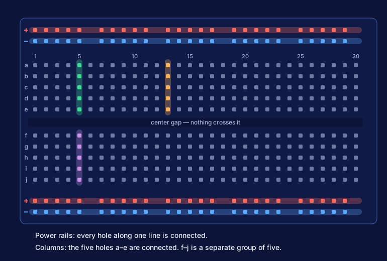
There are only two kinds of strip.
The columns in the middle. Each numbered column has five holes above the center gap, lettered a to e, and five below it, lettered f to j. The five holes a–e of one column are connected to each other. So are the five holes f–j. The two groups are not connected to each other, and no column is connected to the column next to it.
The power rails along the edges. The long lines marked with a red + and a blue − run sideways. Every hole along one line is connected. You connect power to one end and then pick it up anywhere along the board.
2. Why there is a gap in the middle
The gap is exactly as wide as a chip is. A chip — or a board with two rows of pins, like your NodeMCU — sits across it, with one row of pins in the top half and the other row in the bottom half. Each pin then has its own strip, with free holes left over in the same column for your wires.
If the gap were not there, each pin on one side would be shorted to the pin facing it.
3. Seat the NodeMCU
Do this with the USB cable unplugged.
- Hold the board with the USB connector pointing off the left end of the breadboard.
- Line up the two rows of pins across the center gap. On the narrow board, the pins land in rows
bandi, leaving rowafree on one side and rowjfree on the other. - Check that every pin is over a hole. It is easy to be one column off at one end.
- Press down evenly with both thumbs, a little at each end in turn, until the board sits flat. It takes more force than you expect the first time.
To take it out later, lift it a little at each end in turn. Pulling from one end bends the pins.
4. Find a pin's column
Every pin on the NodeMCU has a label printed next to it: 3V3, GND, D1, A0 and so on. To connect a wire to a pin, you do not touch the pin. You push the wire into a free hole in the same column, on the same side of the gap.
Try it now, still unplugged:
- Find a pin labeled
GNDon the board. - Look at the free hole in the same column — row
aif the pin is in the top half, rowjif it is in the bottom half. - Push one end of a jumper wire into that hole. The other end of that wire is now
GND.
5. Set up the power rails
Almost every circuit in this course needs 3.3 volts and ground in several places. Instead of crowding the two pins, you bring them out to the rails once.
| From | To |
|---|---|
NodeMCU 3V3 |
+ rail (red line) |
NodeMCU GND |
− rail (blue line) |
Use a red wire for 3V3 and a black or blue one for GND if you have them. The board does not care about the color of a wire, but you will, the first time you have twelve of them on the table.
From here on, when a lesson says "to 3V3" or "to GND", any hole on that rail will do.
6. Two things that catch everyone once
Split rails. On many 830-point breadboards the power rails are broken in the middle: the left half and the right half are separate strips. Look at the red and blue lines printed on yours. If the line stops and starts again halfway along, the rail is split. Bridge each one with a short wire across the break, or keep your circuit on the same half as the power wires.
The two rails are not connected to each other. The + rail at the top and the + rail at the bottom are separate until you join them with a wire. Powering the top rail does nothing for the bottom one.
If it didn't work
The board will not go in. One or more pins are resting on plastic between holes. Lift it, check both ends, and try again. Do not force a board that is sitting crooked.
The board covers every hole and there is nowhere to put a wire. You have the wide version of the NodeMCU. Put two breadboards side by side, with one row of pins in each, or plug male-to-female jumper wires straight onto the pins instead.
A wire feels loose in its hole. Jumper wire pins vary in thickness and the clips wear with use. Move to another hole in the same strip. A loose wire causes the most confusing kind of fault: one that comes and goes when you touch the table.
I can't tell whether my rails are split. If the printed lines give no hint, assume they are, and bridge them. An extra bridge wire on a rail that was already continuous changes nothing.